
Pseudostatic RAM (AKA PSRAM) as described on Wikipedia is, in short,
PSRAM or PSDRAM is dynamic RAM with built-in refresh and address-control circuitry to make it behave similarly to static RAM (SRAM). It combines the high density of DRAM with the ease of use of true SRAM.
The WROOM-32 based ESP32 development boards are quite versatile but they are lacking PSRAM as standard. Whereas the newer WROVER boards ship with PSRAM as the norm and is typically 4MB (megabytes) in size, but the WROVER based development boards are unfortunately almost double the cost of the WROOM-32 based development boards.
Laboris documented a successful upgrade of a ESP-WROOM-32 @ Info Upgrade ESP32 board without psRAM with 4MB/8MB SPIRAM
Sooooo, having a bunch of Lolin32 Lites at hand and a bunch of newly acquired IPUS IPS6404L-SQ SPI/QPI PSRAM, I thereby decided to give it a go. Not willing to wait until my 16MB (megabyte) flash chips arrived – my original plan was to replace them as well, which would have given a grand total of 16MB Flash/8MB PSRAM plus the original 520KB of internal SRAM, but alas impatience got the better of me and I hastily forged ahead keeping the original 4MB of flash in place.
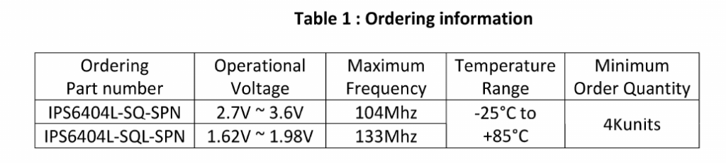
The IPS6404L-SQ PSRAM datasheet
specifies that the PSRAM is available as a 1.8v or a 3.3v variant.
IPUS IPS6404L-SQ PSRAM Chip Variants
By way of flash storage the Lolin32 Lite uses the 32Mbit (4MB) 3V Winbond W25Q32JVSSIG (datasheet, click here)
and as the plan was to piggyback the PSRAM directly on to the back of the Winbond flash chip, I would need to use the matching 3V part, namely the IPS6404L-SQ-SPN version of the PSRAM and luckily that is what I have to hand, 48 of them @ £0.60 each, which per unit is actually cheaper than a 23lc1024-i/sn 1024Kbit SPIRAM part, and yes you can use the PSRAM as box standard SPIRAM.IPS6404L-SQ commands

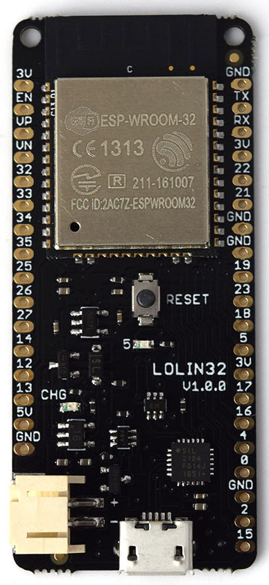
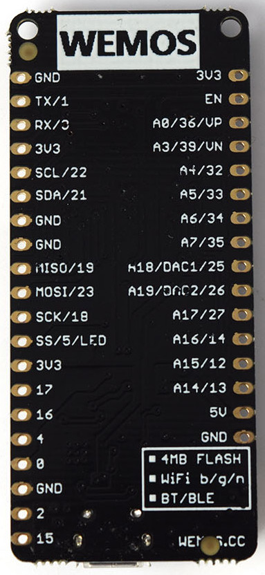
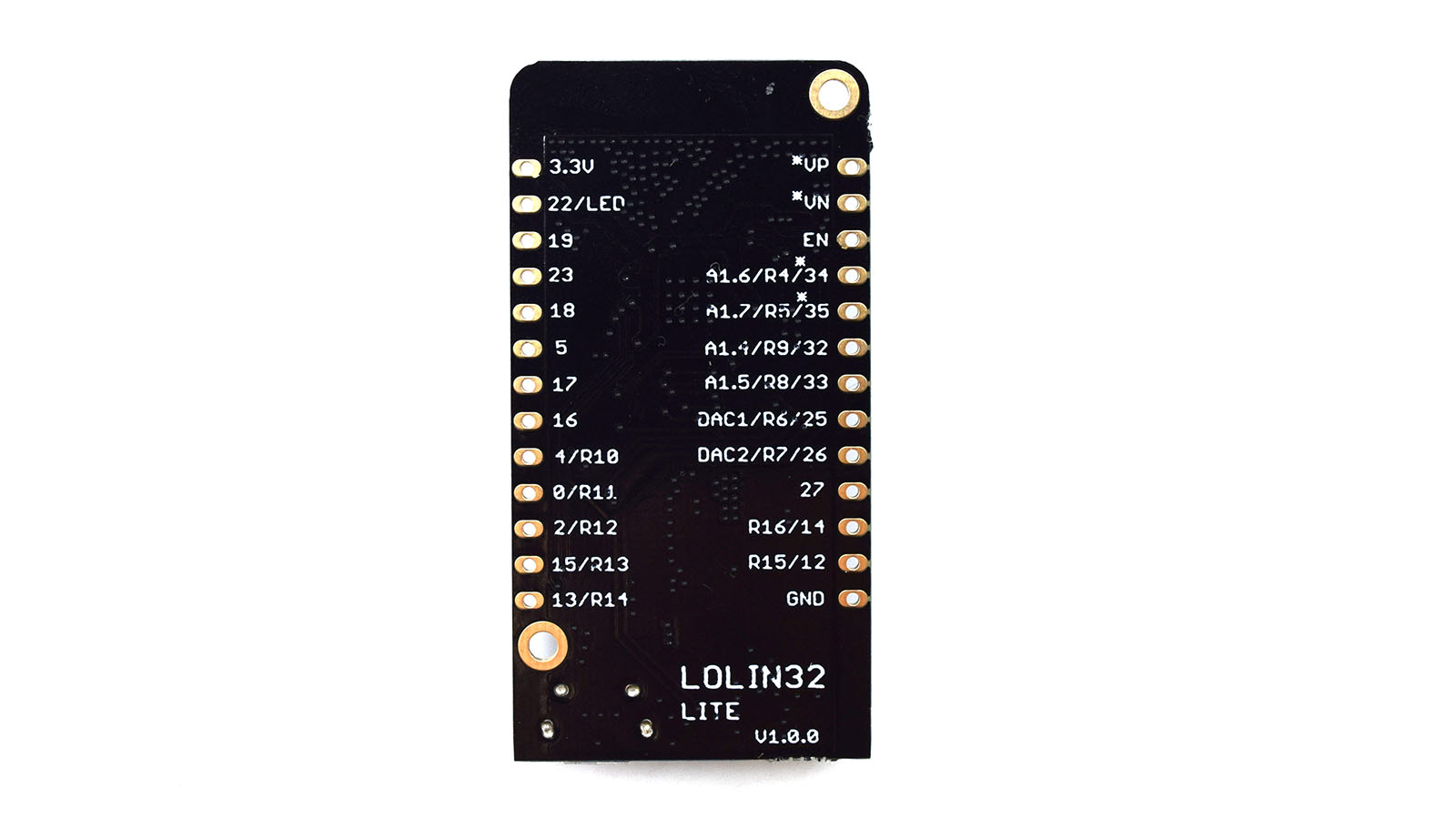
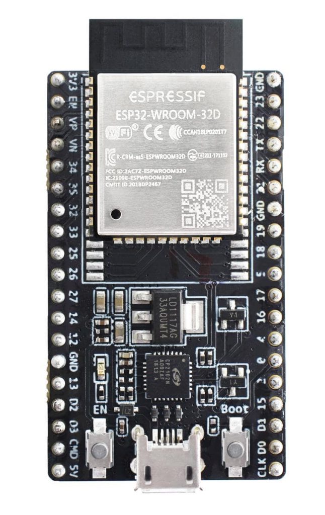
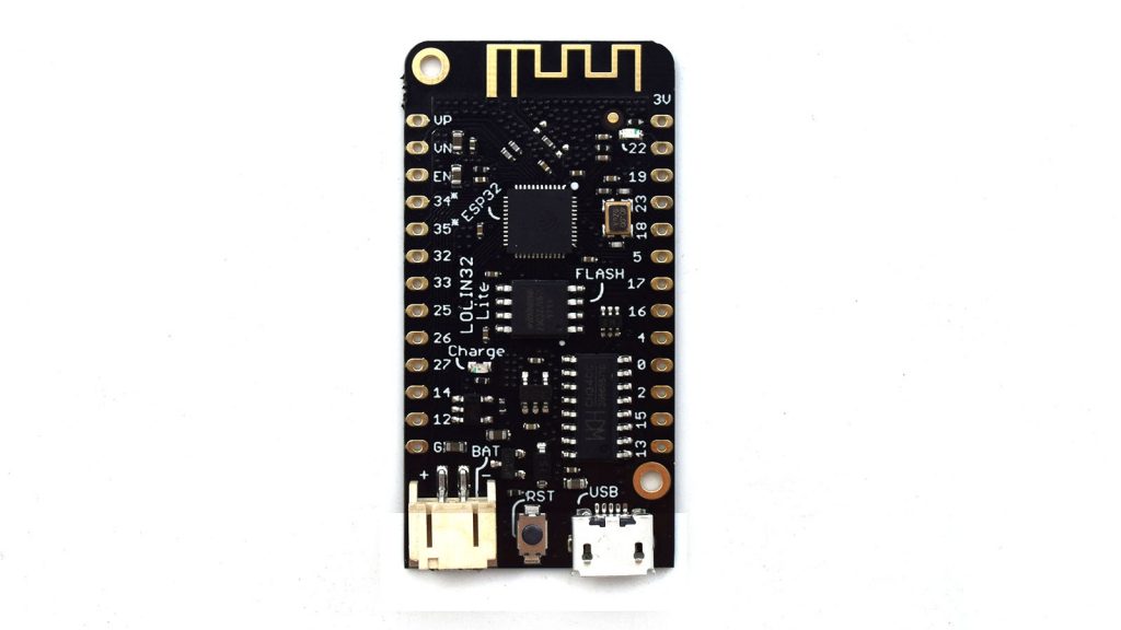
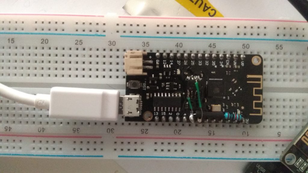
Piggybacking an IC does mean having access to it (the IC), and the Lolin32 Lite, by not using a WROOM-32 module and having a custom design (unlike the DevkitC), has all the ICs exposed (and hence the reason I use them). Actually if you dismantled and piggybacked a WROOM-32 module you wouldn’t be able to refit the Can.
espressif-esp32-devkitc with Can removed ESP32-DevKitC-32D_t with Can fitted Lolin32 Lite, ICs exposed

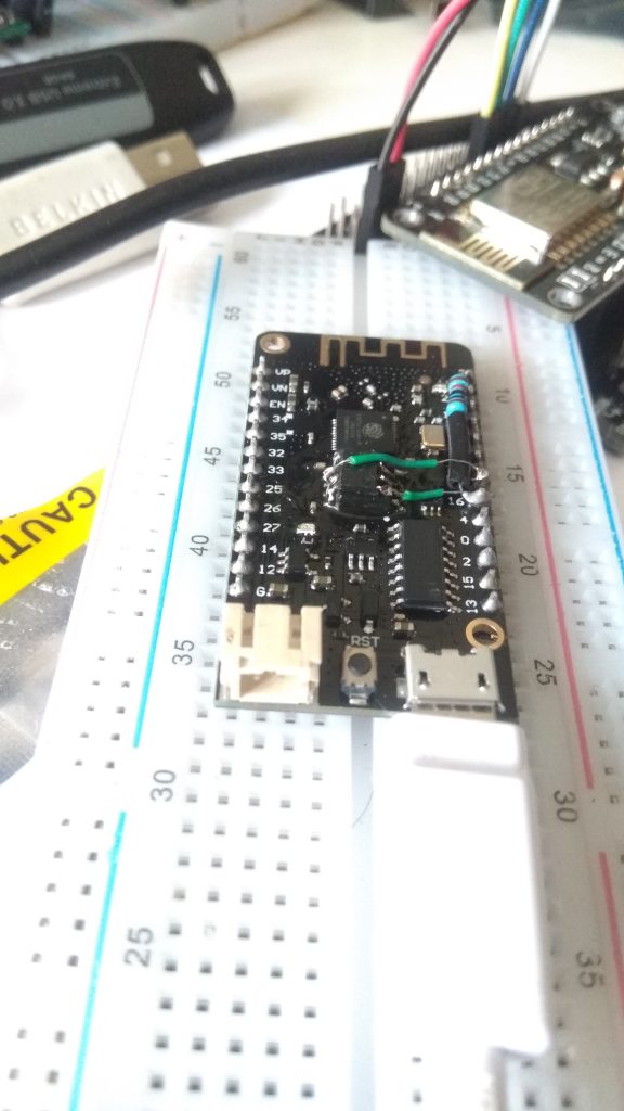
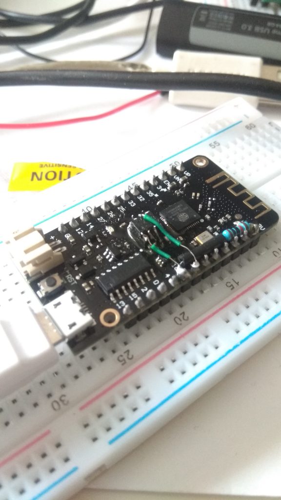
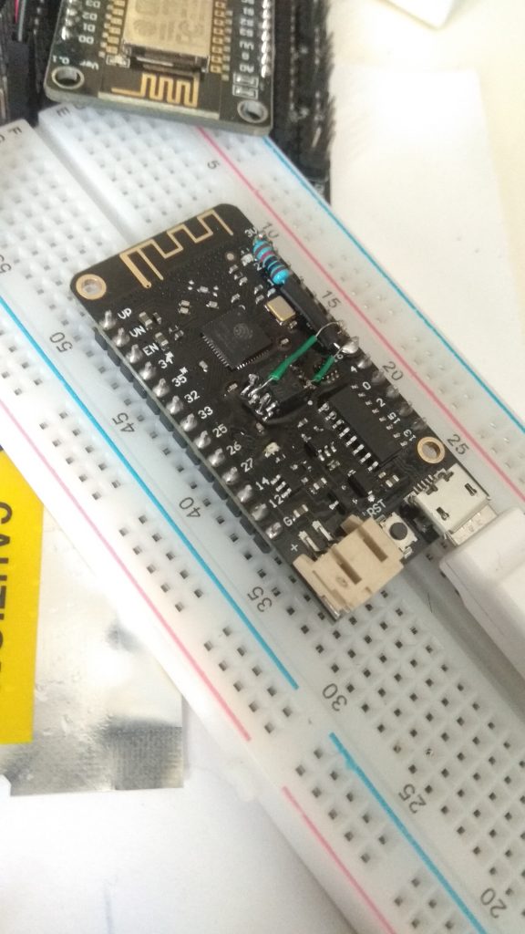
To perform the piggyback, just place the PSRAM on top of the Flash chip, in the correct orientation (i.e. Pin 1 to Pin 1, Pin 8 to Pin 8) and solder all pins excepting –
- Pin 1 – CE/CS
- Pin 6 – SCK
Piggyback diagram

Pins 1, 6 and the 10K pull up are specific to the PSRAM (and the flash which has its own pin 1,pin 6 and resister pullup) and allow the two devices to be controlled individually.
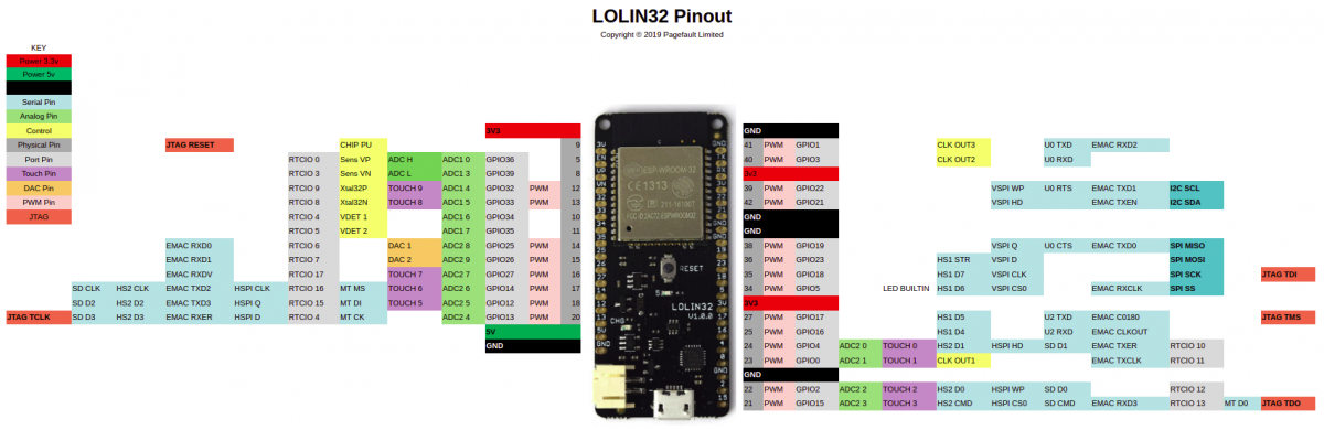
- Pin 1 should be wired to GPIO16 and provides the Chip Select for the PSRAM.
- Pin 6 should be wired to GPIO17 and provides the SCLK for the PSRAM.
- GPIO16 should be pulled up to 3V via a 10K resistor to ensure that the PSRAM is deselected during boot up.
NOTE: GPIO16 and GPIO17 will no longer be available for normal use after fitting the the PSRAM!!! Yes you just lost two pins!
Piggybacked PSRAM Piggybacked PSRAM Piggybacked PSRAM Piggybacked PSRAM
As to enabling the PSRAM in PlatformIO, all that is required is to simply add the following PSRAM related build defines to your “platformio.ini” file.
|
1 |
build_flags = -DBOARD_HAS_PSRAM -mfix-esp32-psram-cache-issue -DLOG_LOCAL_LEVEL=ESP_LOG_DEBUG -DCORE_DEBUG_LEVEL=ARDUHAL_LOG_LEVEL_DEBUG |
After which you should hopefully see a message saying “PSRAM enabled”
PSRAM Enabled – Going so fast it’s blurry 🙂
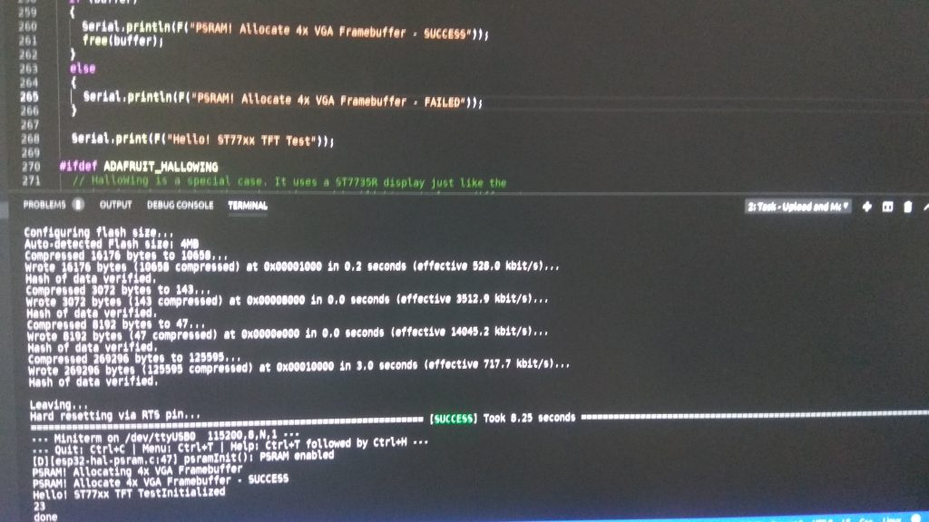
Assuming that your PSRAM is enabled and active, you will now be able to use 4MB of the 8MB PSRAM as normal addressable memory, which you can subsequently allocate and use with the “ps_malloc” function.
|
1 2 3 4 5 6 7 8 9 |
char* buffer = (char) ps_malloc(2*1024*1024); if (buffer) { Serial.println(F("PSRAM! Allocate 2MB - Success")); } else { Serial.println(F("PSRAM! Allocate 2MB - Failed")); } |
What about the remaining 4MB, I hear you say, well the remaining 4MB of the 8MB PSRAM is accessible using the ESP32 High mem Allocation API,
a form of bank switching, where sections of ram are mapped in and out of the same address space, all of which takes me back to the good old bank switching days of Commodore 128s and Atari 130XEs, but I digress. An example doing a simple memory test of the high memory range is available at esp-idf: system/himem
Links
ESP32-IDF: Support for external RAM