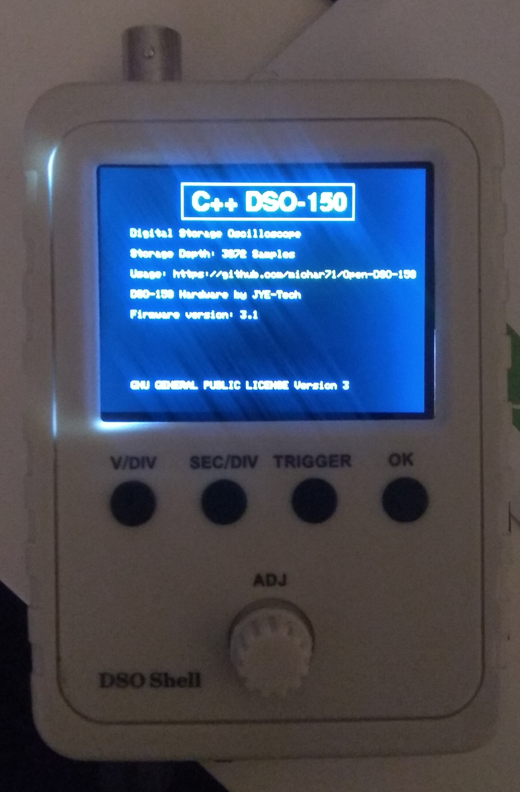
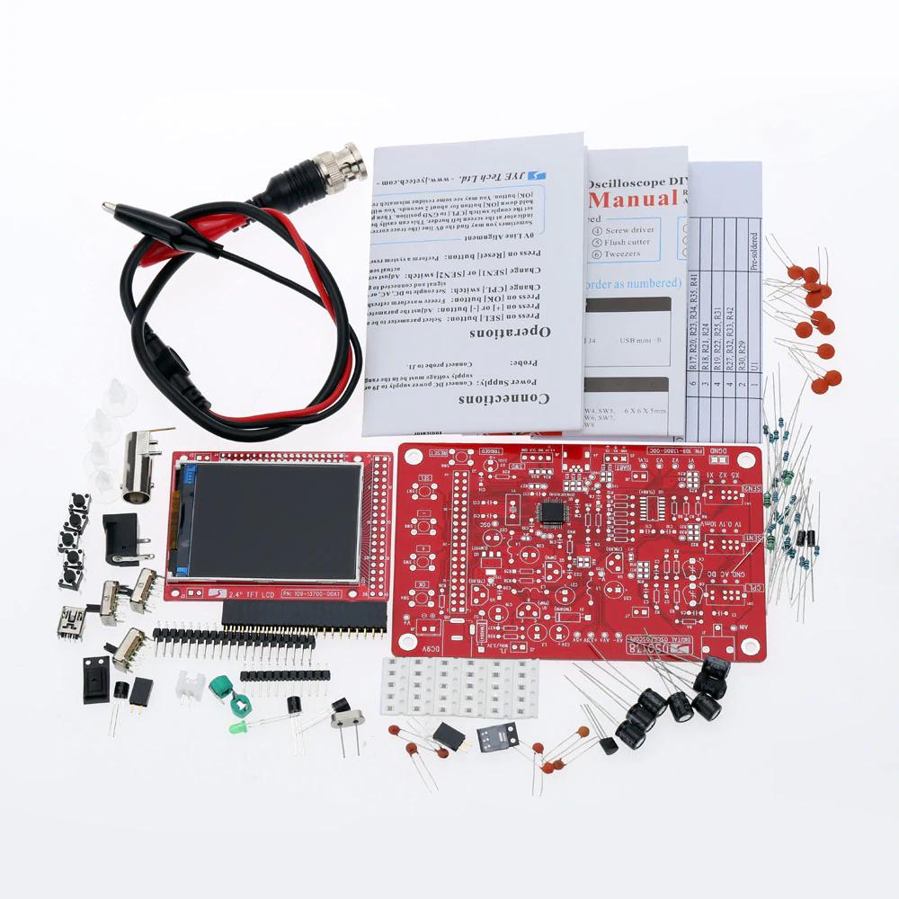
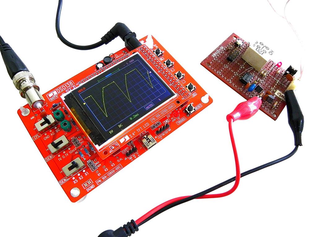
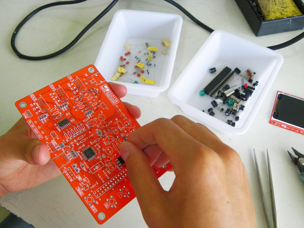
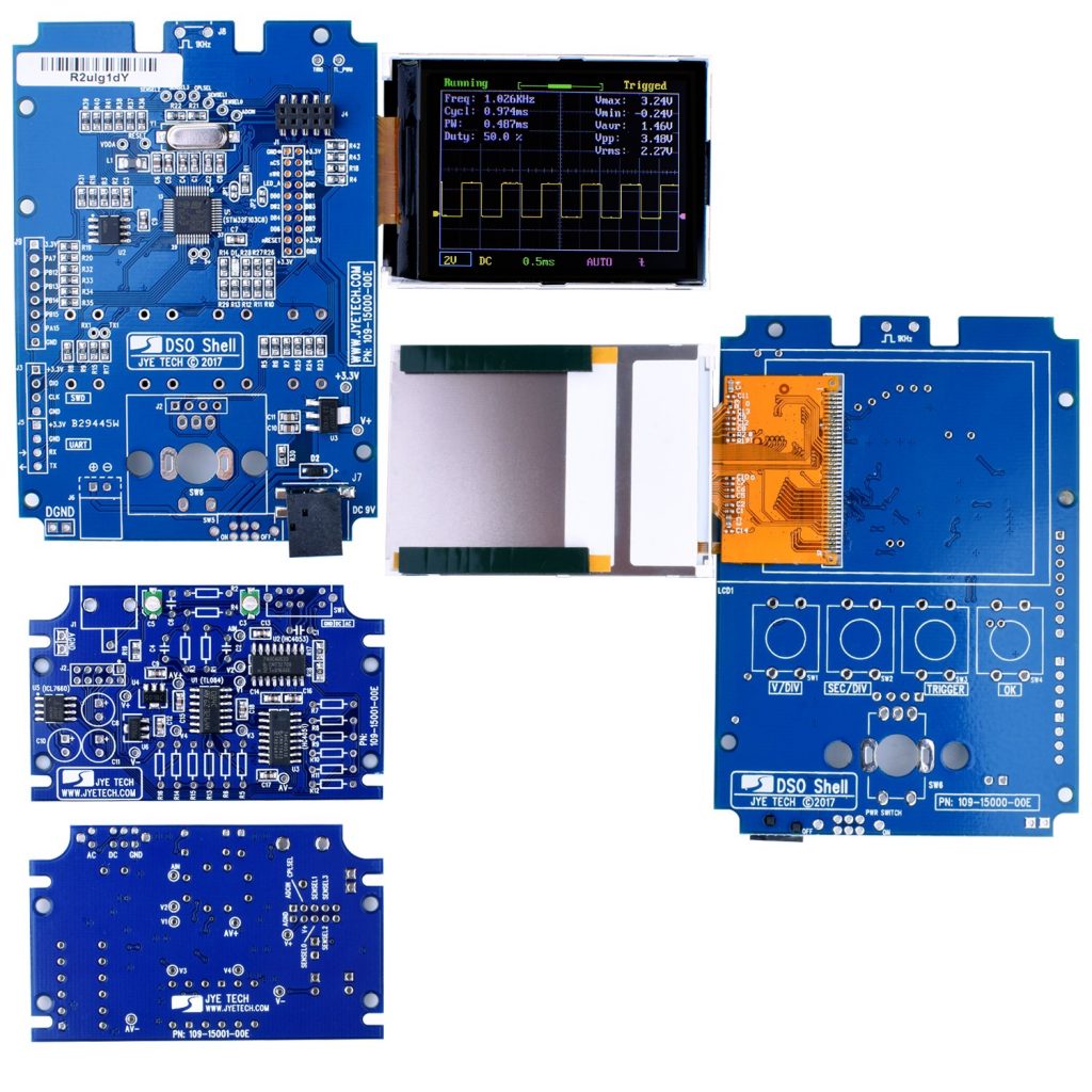
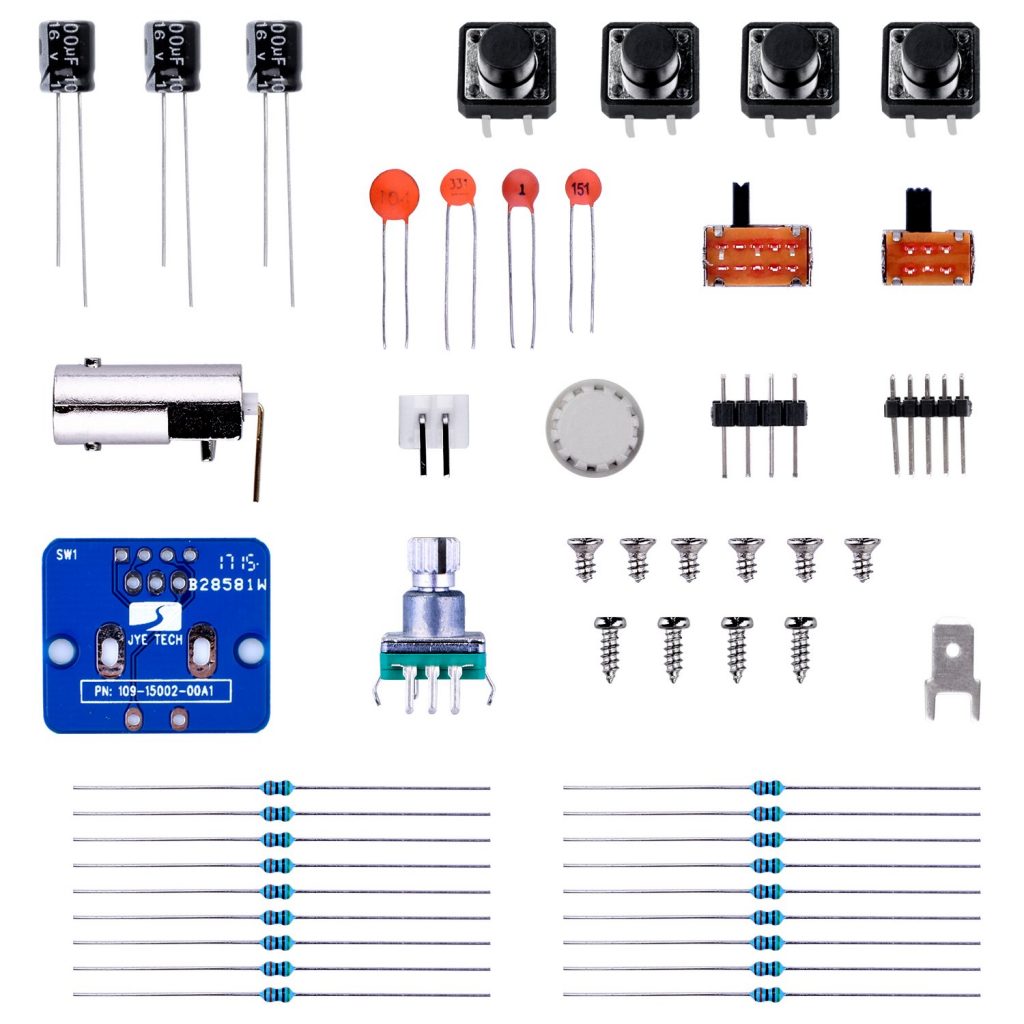
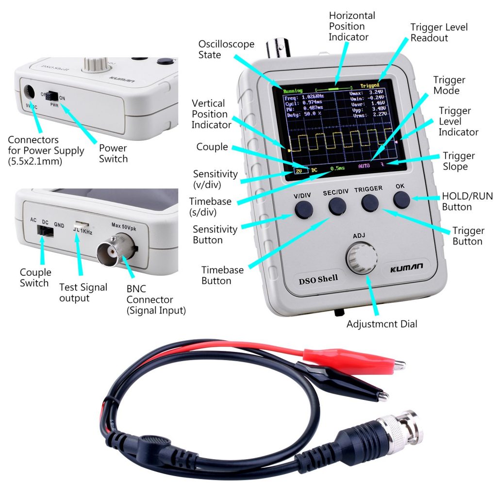
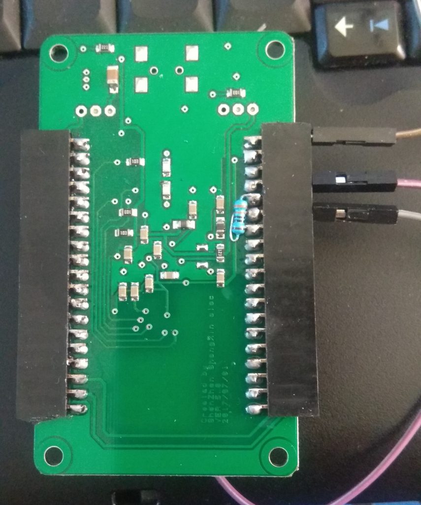
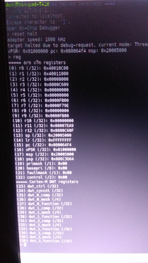
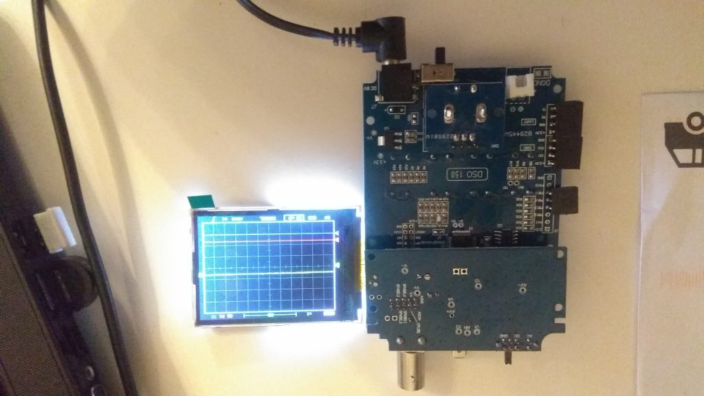
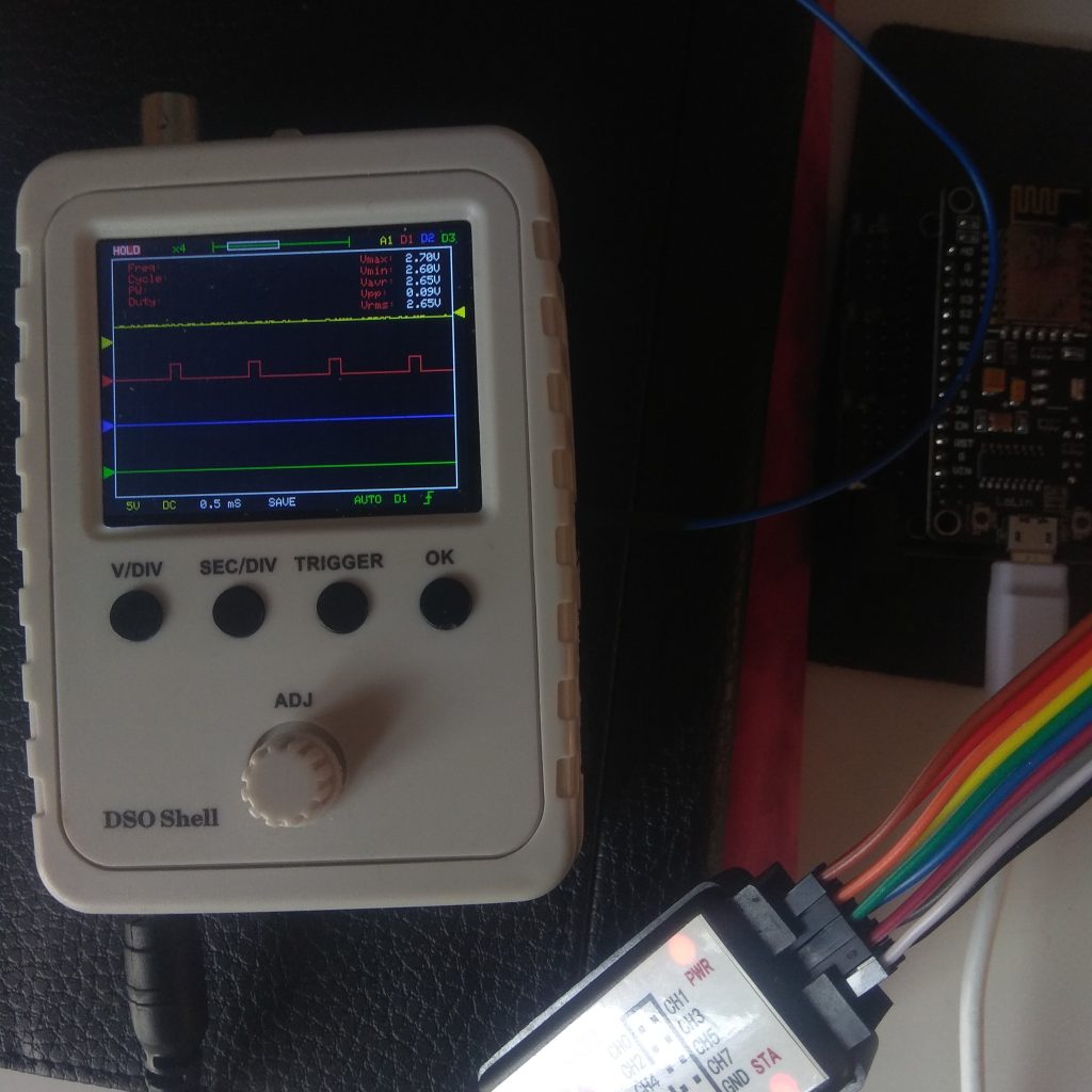
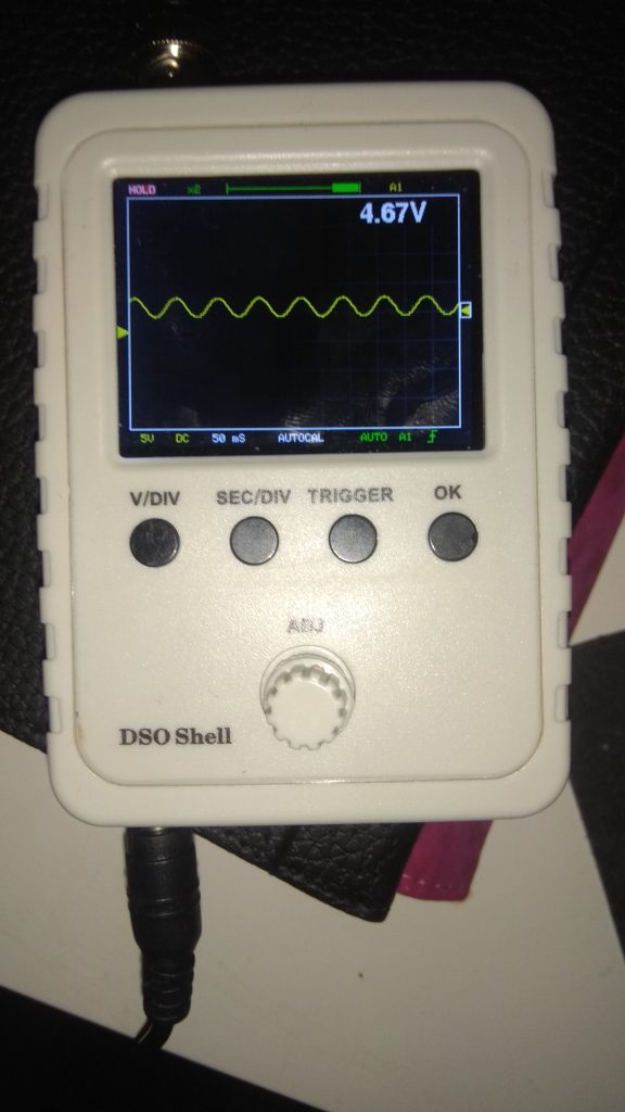
For some time I have been aware of the little portable oscilloscopes (DSO) kits produced by JYE Tech, such as the DSO-138 and DSO-150. While these kits can be purchased fully built, they are usually sold in a DIY state of “you solder everything” or “you solder everything minus the smd components”. In the images below, the red PCB is the DSO-138 and the blue PCB is the big brother DSO-150.
I required a portable oscilloscope for some analog related projects, but I also wanted the ability to capture digital output at the same time. In the absence of digital outputs, I kept putting off the purchase until happily, I came across a couple of Github projects where the firmware has been rewritten and enhanced for both the DSOs mentioned. They both now have support for digital channels. That is if you are willing to flash the new firmware.
The Open source DSO-138 features support for 2 analog + 2 digital channels. A second analog channel requires hardware mods to the pcb.

DSO-138: An open source firmware for DSO-138 O-Scope
Summary
DSO-138 is an excellent piece of hardware based on ARM Cortex M3 core STM32F103 processor and sufficient for most beginner users. The stock firmware, while quite responsive, can use a few improvements. The main shortcoming which prompted the development of DLO-138 firmware is the inability to get waveform data into a computer for further analysis and the lack of a second channel. Engineers troubleshooting hardware issues need to mark reference points on waveform so having another analog or digital channel can greatly improve analysis. This firmware hopes to improve on these issues.
Features
- Two analog channels
- Two digital logic channels (SWDIO and SWDIO pins (PA13 and PA14) on board)
- Serial port interface for captured waveform data
- Trigger source selectable from Analog Channel 1 or Digital Channel
- Option to use rotary encoder instead of + – and SEL switches
- 2K sample depth
This firmware can be used on stock DSO-138 hardware as well. Select one of the pre-compiled binaries to suit the board. Follow the firmware upgrade instructions for DSO-138. At any time, you can reflash DSO-138 with JYE Tech provided firmware.
Cost
Extra features come at an additional cost. In the case of DLO-138, it is the loss of lowest timebase. Maximum sampling rate in DLO-138 is 20 µs/div instead of 10 µs/div. In the 20 µs/div range, firmware under-samples ADC channels, often reading same data twice. To use the second analog channel, analog front end has to be duplicated on a daughter board. On a stock hardware, this firmware can be used to provide two digital logic channels.
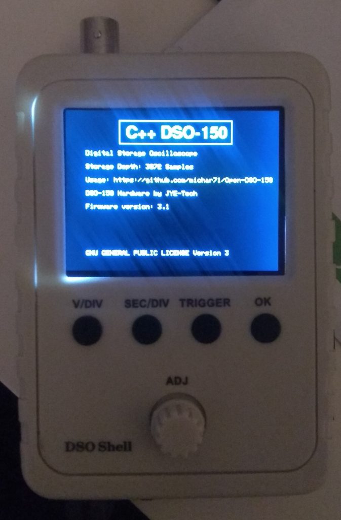
The Open source DSO-150 features support for 1 analog + 3 (yes 3) digital channels.
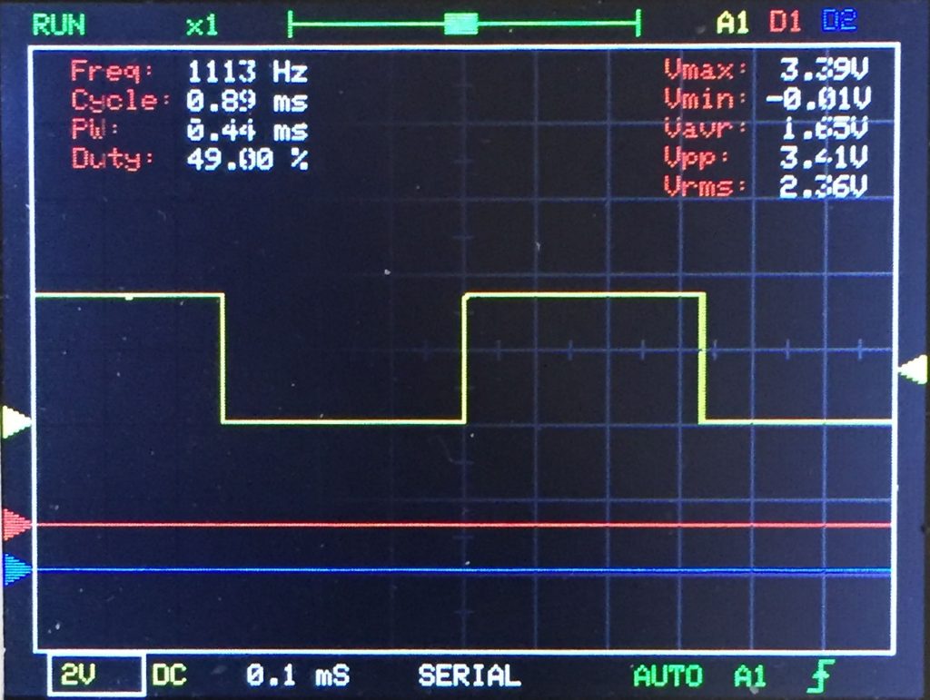
DSO-150: An open source firmware for JYE Tech DSO-150 Digital Storage Oscilloscope
Summary
Complete rewrite of DSO-150 Firmware
- No longer DSO-138 compatible (Sorry…)
- Rewritten for Atollic trueSTUDIO (Yea… Real debugging)
- Now using internal digital trigger through ADC IRQ (So trigger level can now be correlated to real voltage)
- Lots of new features like voltage overlay, markers, auto cal
Features
- Support 1 Analog and up to 3 Digital Channels
- Trigger on rising/falling/both edges
- Trigger on Analog, Digital 1,2,3 Signal
- Single/Norm/Auto Trigger Mode
- Exact trigger voltage
- Serial Data Dump
- Automatic Zero-Level Cal for all gain-stages
- Voltmeter mode (Averaged over last 10 samples)
- Signal Statistics Display
- Cursors for Analog Signal
- Load/Store Waveform to/from Flash
- Zoom Out Display (See more data with full sampling Rate)
- “Persistence” Mode
- Variable Signal Size for Digital Signal Waveform
- “loop” mode to scroll current input-values
- AC/DC mode
- 3K Sampling Depth
- Buttons not blocked during sampling
After discovering the availability of the enhanced firmware, I bit the bullet and decided to get a DSO-150. Not looking forward to doing that much soldering, I therefore chose yet another purchase option of DIY “pre-soldered, just pop everything into the case on arrival”.
The instructions of building and flashing the DSO-Firmware are included in the github page, but as things never go smoothly, I had to
- Convert the built binary to HEX format
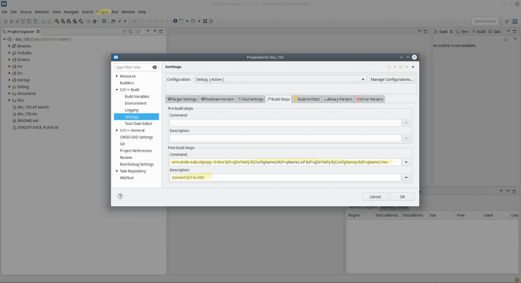
After building the project in TrueStudio you will be left with an ELF binary file. To be able to update the firmware the ELF file will have to be in HEX file format. This can be easily achieved by adding a post build step to the project.
The post build command is
|
1 |
arm-atollic-eabi-objcopy -O ihex ${ProjDirPath}/${ConfigName}/${ProjName}.elf ${ProjDirPath}/${ConfigName}/${ProjName}.hex |
and the post build description can be whatever you like, in my case
|
1 |
Convert ELF to HEX |
So now when you build the project you will end up with both an ELF file and a HEX file. The HEX file is what you will flash to the DSO.
- Flashing the device.
I tried to flash the device via the on board USART1 with both Linux and Windows using the tools,
- stm32flash (linux) – Open source flash program for STM32 using the ST serial bootloader. @ https://sourceforge.net/projects/stm32flash/
Download stm32flash with git.
|
1 |
$ git clone https://git.code.sf.net/p/stm32flash/code stm32flash-code |
- FLASHER-STM32 (windows) – STM32 Flash loader demonstrator (UM0462) @ https://www.st.com/b/en/development-tools/flasher-stm32.html
- DSO-150 flashing instructions – Flashing Guide
- DSO-150 flashing instructions – Flashing Guide
But the device was not recognised with the message,
No response from the target, Bootloader cannot be started
I eventually concluded that the required Serial bootloader was missing and gave up on UART flashing, deciding instead to flash via STLink/JTAG port. But not having an STLink handy, I decided to flash it with my FTDI FT2232H device and openocd on Linux.
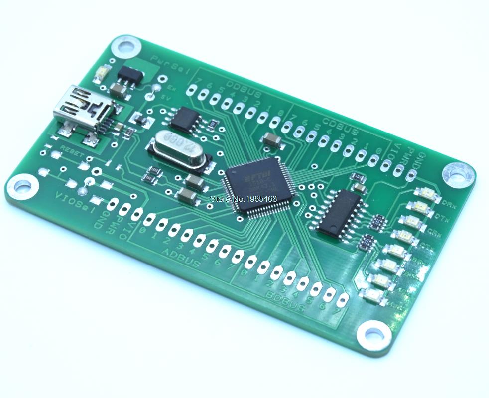
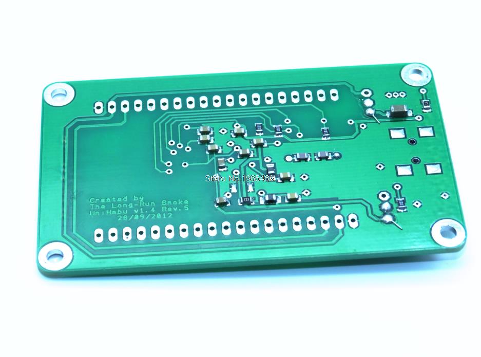
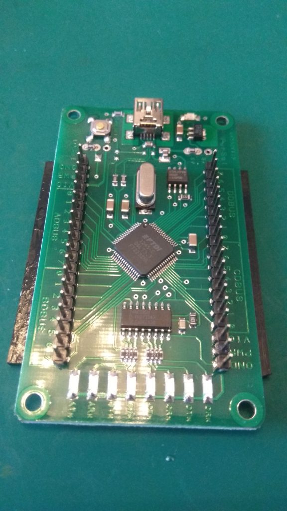
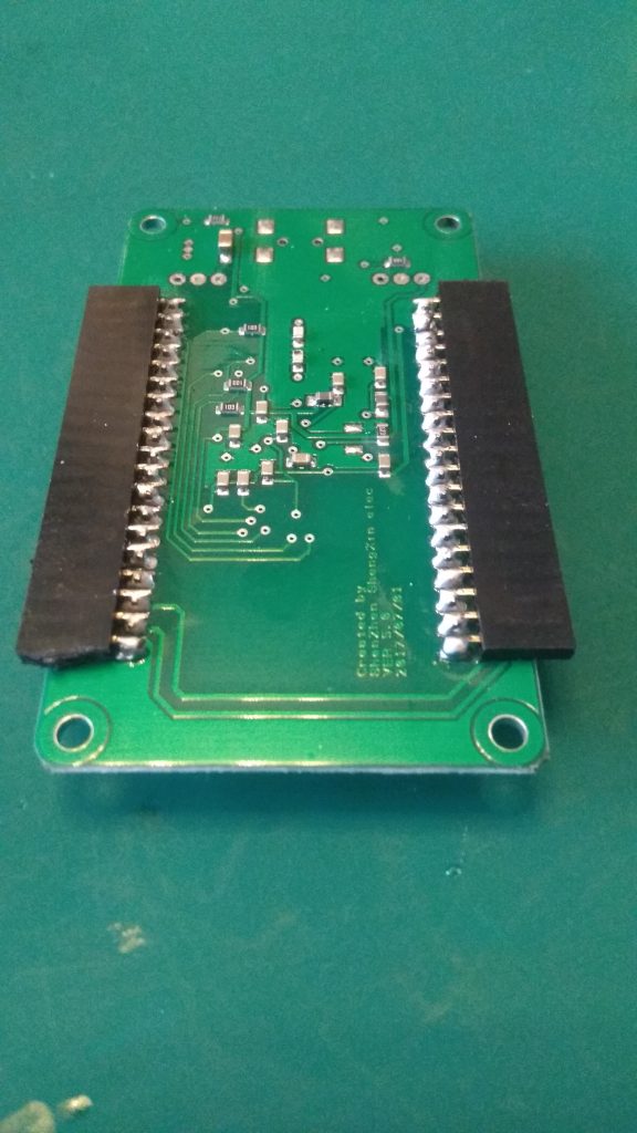
The FTDI device is readily available in various flavours at various outlets including Ebay, Aliexpress, and Amazon. Mine is shown below.
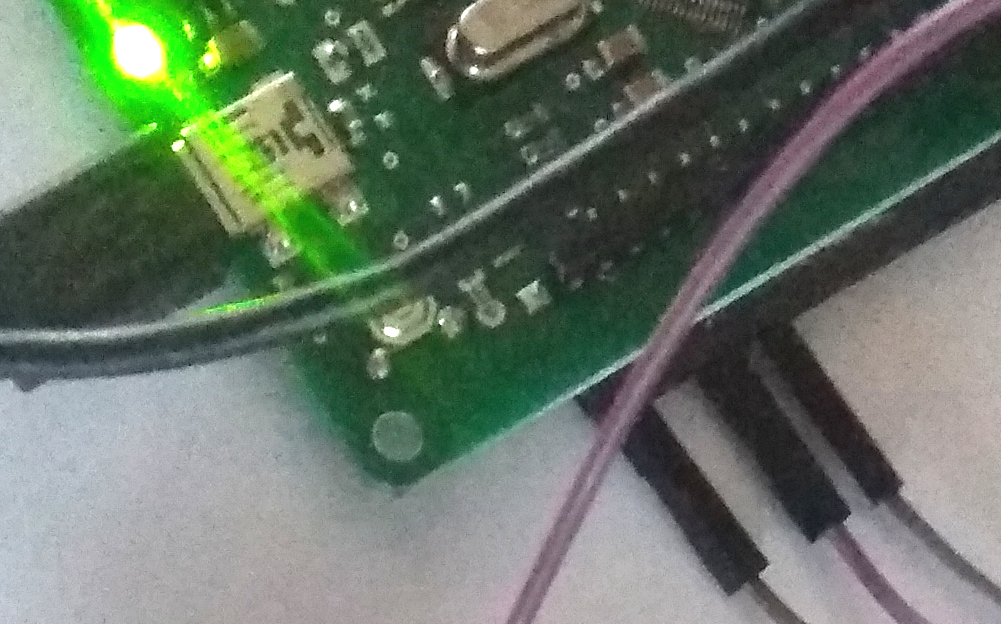
Plugging in the FT2232HL gives you a satisfying,
|
1 2 3 4 5 6 7 8 9 10 11 12 13 14 15 16 17 18 |
[ 7247.588043] usb 2-1.2: new high-speed USB device number 8 using ehci-pci [ 7247.702046] usb 2-1.2: New USB device found, idVendor=0403, idProduct=6010 [ 7247.702050] usb 2-1.2: New USB device strings: Mfr=1, Product=2, SerialNumber=3 [ 7247.702054] usb 2-1.2: Product: USB <-> Serial Converter [ 7247.702057] usb 2-1.2: Manufacturer: FTDI [ 7247.702060] usb 2-1.2: SerialNumber: FT2BM8Q0 [ 7247.705291] ftdi_sio 2-1.2:1.0: FTDI USB Serial Device converter detected [ 7247.705366] usb 2-1.2: Detected FT2232H [ 7247.705771] usb 2-1.2: FTDI USB Serial Device converter now attached to ttyUSB1 [ 7247.708587] ftdi_sio 2-1.2:1.1: FTDI USB Serial Device converter detected [ 7247.708633] usb 2-1.2: Detected FT2232H [ 7247.709110] usb 2-1.2: FTDI USB Serial Device converter now attached to ttyUSB2 [ 7292.457478] ftdi_sio ttyUSB1: FTDI USB Serial Device converter now disconnected from ttyUSB1 [ 7292.457520] ftdi_sio 2-1.2:1.0: device disconnected [13411.858946] usb 2-1.2: USB disconnect, device number 8 [13411.859398] ftdi_sio ttyUSB2: FTDI USB Serial Device converter now disconnected from ttyUSB2 [13411.859433] ftdi_sio 2-1.2:1.1: device disconnected |
All About Circuits have a good primer on using and FTDI witth openocd @ https://www.allaboutcircuits.com/technical-articles/getting-started-with-openocd-using-ft2232h-adapter-for-swd-debugging/
I would follow their guide referring back here for DSO-150 specifics 🙂
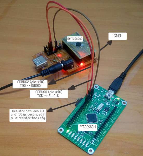
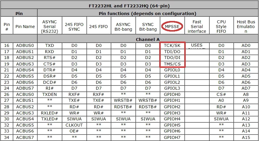
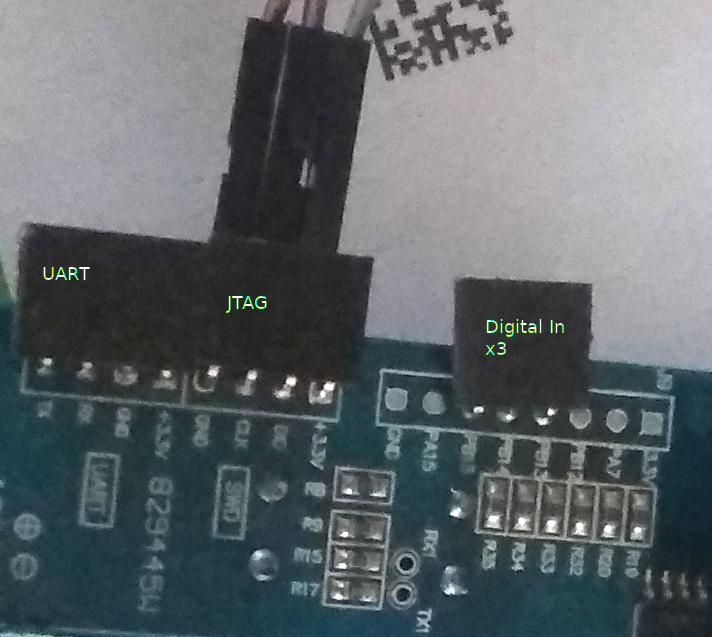
I soldered on some header pins to the FT2232HL and DSO-150.
Now the wiring was complete I installed openocd and moved on to setting up the configuration files required by openocd
- /usr/share/openocd/scripts/interface/ftdi/myft2232hl.cfg
|
1 2 3 4 5 6 7 8 9 10 11 12 13 14 15 16 |
#This configuration file is created for a tutorial: #”Getting Started with OPENOCD Using FT2232H Adapter for SWD Debugging” #Written by:Yahya Tawil - yahya.tawil_at_gmail.com #Pulished on: http://www.allaboutcircuits.com #Version of OpenOCD:0.9.0 interface ftdi transport select swd ftdi_vid_pid 0x0403 0x6010 #ftdi_device_desc "USB Serial Converter A" #ftdi_device_desc "FT2232H 开发板" ftdi_serial "FT2BM8Q0" #adapter_khz 8 ftdi_layout_init 0x0018 0x05fb ftdi_layout_signal SWD_EN -data 0 ftdi_layout_signal nSRST -data 0x0010 |
|
1 |
ftdi_serial "FT2BM8Q0" |
is the number from the dmesg log!
|
1 |
[ 7247.702060] usb 2-1.2: SerialNumber: FT2BM8Q0 |
- /usr/share/openocd/scripts/target/stm32f1x.cfg
|
1 2 3 4 5 6 7 8 9 10 11 12 13 14 15 16 17 18 19 20 21 22 23 24 25 26 27 28 29 30 31 32 33 34 35 36 37 38 39 40 41 42 43 44 45 46 47 48 49 50 51 52 53 54 55 56 57 58 59 60 61 62 63 64 65 66 67 68 69 70 71 72 73 74 75 76 77 78 79 80 |
# script for stm32f1x family # # stm32 devices support both JTAG and SWD transports. # source [find target/swj-dp.tcl] source [find mem_helper.tcl] if { [info exists CHIPNAME] } { set _CHIPNAME $CHIPNAME } else { set _CHIPNAME stm32f1x } set _ENDIAN little # Work-area is a space in RAM used for flash programming # By default use 4kB (as found on some STM32F100s) if { [info exists WORKAREASIZE] } { set _WORKAREASIZE $WORKAREASIZE } else { set _WORKAREASIZE 0x1000 } #jtag scan chain if { [info exists CPUTAPID] } { set _CPUTAPID $CPUTAPID } else { if { [using_jtag] } { # See STM Document RM0008 Section 26.6.3 set _CPUTAPID 0x3ba00477 } { # this is the SW-DP tap id not the jtag tap id set _CPUTAPID 0x1ba01477 } } swj_newdap $_CHIPNAME cpu -irlen 4 -ircapture 0x1 -irmask 0xf -expected-id $_CPUTAPID if {[using_jtag]} { jtag newtap $_CHIPNAME bs -irlen 5 } set _TARGETNAME $_CHIPNAME.cpu target create $_TARGETNAME cortex_m -endian $_ENDIAN -chain-position $_TARGETNAME $_TARGETNAME configure -work-area-phys 0x20000000 -work-area-size $_WORKAREASIZE -work-area-backup 0 # flash size will be probed set _FLASHNAME $_CHIPNAME.flash flash bank $_FLASHNAME stm32f1x 0x08000000 0 0 0 $_TARGETNAME # JTAG speed should be <= F_CPU/6. F_CPU after reset is 8MHz, so use F_JTAG = 1MHz adapter_khz 1000 adapter_nsrst_delay 100 if {[using_jtag]} { jtag_ntrst_delay 100 } reset_config srst_nogate if {![using_hla]} { # if srst is not fitted use SYSRESETREQ to # perform a soft reset cortex_m reset_config sysresetreq } $_TARGETNAME configure -event examine-end { # DBGMCU_CR |= DBG_WWDG_STOP | DBG_IWDG_STOP | # DBG_STANDBY | DBG_STOP | DBG_SLEEP mmw 0xE0042004 0x00000307 0 } $_TARGETNAME configure -event trace-config { # Set TRACE_IOEN; TRACE_MODE is set to async; when using sync # change this value accordingly to configure trace pins # assignment mmw 0xE0042004 0x00000020 0 } |
If you have wired up the FTDI FT2232H (or whichever) correctly then running openocd should give you,
|
1 2 3 4 5 6 7 8 9 10 11 12 13 |
$ sudo openocd -f interface/ftdi/myft2232hl.cfg -f target/stm32f1x.cfg Open On-Chip Debugger 0.10.0 Licensed under GNU GPL v2 For bug reports, read http://openocd.org/doc/doxygen/bugs.html Info : FTDI SWD mode enabled adapter speed: 1000 kHz adapter_nsrst_delay: 100 none separate cortex_m reset_config sysresetreq Info : clock speed 1000 kHz Info : SWD DPIDR 0x1ba01477 Info : stm32f1x.cpu: hardware has 6 breakpoints, 4 watchpoints |
I forgot to take notes at the time of flashing, but I remember having to unprotect the flash!
Update: This post describes in detail the process of flashing a STM32 Cortex M3 with openocd 🙂 https://jacobmossberg.se/posts/2017/01/10/using-openocd-flash-arm-cortex-m3.html
These are the commands I executed during the process of flashing.
|
1 2 3 4 5 6 7 8 9 10 11 12 13 14 15 16 17 18 19 20 21 22 23 24 25 26 27 28 29 30 31 32 33 34 35 36 37 38 39 40 41 42 43 44 45 46 47 48 49 50 51 52 53 54 55 56 57 58 59 60 61 62 63 64 65 66 67 68 69 70 71 72 73 74 75 76 77 78 79 80 81 82 83 84 85 86 87 88 89 90 91 92 93 94 95 96 97 98 99 100 |
$ sudo openocd -f interface/ftdi/myft2232hl.cfg -f target/stm32f1x.cfg Open On-Chip Debugger 0.10.0 Licensed under GNU GPL v2 For bug reports, read http://openocd.org/doc/doxygen/bugs.html Info : FTDI SWD mode enabled adapter speed: 1000 kHz adapter_nsrst_delay: 100 none separate cortex_m reset_config sysresetreq Info : clock speed 1000 kHz Info : SWD DPIDR 0x1ba01477 Info : stm32f1x.cpu: hardware has 6 breakpoints, 4 watchpoints $ telnet localhost 4444 Trying 127.0.0.1... Connected to localhost. Escape character is '^]'. Open On-Chip Debugger > history reset halt reg flash info 0 flash list flash banks quit exit > flash info 0 device id = 0x20036410 flash size = 64kbytes #0 : stm32f1x at 0x08000000, size 0x00010000, buswidth 0, chipwidth 0 # 0: 0x00000000 (0x400 1kB) not protected # 1: 0x00000400 (0x400 1kB) not protected # 2: 0x00000800 (0x400 1kB) not protected # 3: 0x00000c00 (0x400 1kB) not protected # 4: 0x00001000 (0x400 1kB) not protected # 5: 0x00001400 (0x400 1kB) not protected # 6: 0x00001800 (0x400 1kB) not protected # 7: 0x00001c00 (0x400 1kB) not protected # 8: 0x00002000 (0x400 1kB) not protected # 9: 0x00002400 (0x400 1kB) not protected # 10: 0x00002800 (0x400 1kB) not protected # 11: 0x00002c00 (0x400 1kB) not protected # 12: 0x00003000 (0x400 1kB) not protected # 13: 0x00003400 (0x400 1kB) not protected # 14: 0x00003800 (0x400 1kB) not protected # 15: 0x00003c00 (0x400 1kB) not protected # 16: 0x00004000 (0x400 1kB) not protected # 17: 0x00004400 (0x400 1kB) not protected # 18: 0x00004800 (0x400 1kB) not protected # 19: 0x00004c00 (0x400 1kB) not protected # 20: 0x00005000 (0x400 1kB) not protected # 21: 0x00005400 (0x400 1kB) not protected # 22: 0x00005800 (0x400 1kB) not protected # 23: 0x00005c00 (0x400 1kB) not protected # 24: 0x00006000 (0x400 1kB) not protected # 25: 0x00006400 (0x400 1kB) not protected # 26: 0x00006800 (0x400 1kB) not protected # 27: 0x00006c00 (0x400 1kB) not protected # 28: 0x00007000 (0x400 1kB) not protected # 29: 0x00007400 (0x400 1kB) not protected # 30: 0x00007800 (0x400 1kB) not protected # 31: 0x00007c00 (0x400 1kB) not protected # 32: 0x00008000 (0x400 1kB) not protected # 33: 0x00008400 (0x400 1kB) not protected # 34: 0x00008800 (0x400 1kB) not protected # 35: 0x00008c00 (0x400 1kB) not protected # 36: 0x00009000 (0x400 1kB) not protected # 37: 0x00009400 (0x400 1kB) not protected # 38: 0x00009800 (0x400 1kB) not protected # 39: 0x00009c00 (0x400 1kB) not protected # 40: 0x0000a000 (0x400 1kB) not protected # 41: 0x0000a400 (0x400 1kB) not protected # 42: 0x0000a800 (0x400 1kB) not protected # 43: 0x0000ac00 (0x400 1kB) not protected # 44: 0x0000b000 (0x400 1kB) not protected # 45: 0x0000b400 (0x400 1kB) not protected # 46: 0x0000b800 (0x400 1kB) not protected # 47: 0x0000bc00 (0x400 1kB) not protected # 48: 0x0000c000 (0x400 1kB) not protected # 49: 0x0000c400 (0x400 1kB) not protected # 50: 0x0000c800 (0x400 1kB) not protected # 51: 0x0000cc00 (0x400 1kB) not protected # 52: 0x0000d000 (0x400 1kB) not protected # 53: 0x0000d400 (0x400 1kB) not protected # 54: 0x0000d800 (0x400 1kB) not protected # 55: 0x0000dc00 (0x400 1kB) not protected # 56: 0x0000e000 (0x400 1kB) not protected # 57: 0x0000e400 (0x400 1kB) not protected # 58: 0x0000e800 (0x400 1kB) not protected # 59: 0x0000ec00 (0x400 1kB) not protected # 60: 0x0000f000 (0x400 1kB) not protected # 61: 0x0000f400 (0x400 1kB) not protected # 62: 0x0000f800 (0x400 1kB) not protected # 63: 0x0000fc00 (0x400 1kB) not protected STM32F10x (Medium Density) - Rev: Y > |
Anyway the take away is that I got it flashed, but not via the UART, I had to use the JTAG port and the new digital inputs are fully functional.
DSO-150 User Instructions – User Guide
DSO-150 How to Upgrade Firmware (Official) – Flashing Guide

